Integrated U-MOT
Integrated U-MOT
A magneto-optical trap (MOT) is the standard starting point for experiments with ultracold atoms. It provides a highly efficient and robust trapping mechanism that can capture and cool room temperature atoms to µK temperatures.
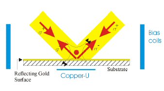 Beam configuration for the Mirror- MOT setup. It can be seen that the reflected beams have the right polarization to form beam pairs of opposite helicity with the incoming beams. The pair of horizontal beams travels perpendicular to the image plane. Also shown are the bias coils creating the horizontal homogeneous magnetic field.
 Since the atom chip blocks the optical access to the trapping area from one direction the standard arrangment of six laser beams can not be used. Instead only four beams are used, two counter-propagating ones parallel to the chip and two hitting the chip under 45 degrees with the chip-surface acting as a mirror for these beams. Because the helicity of the beams is inverted by the reflection the incoming and reflected beams form two perpendicular pairs of beams with correct polarization in the region where all beams overlap. Together with the horizontal beam pair the standard six-beam configuration is restored in this area.
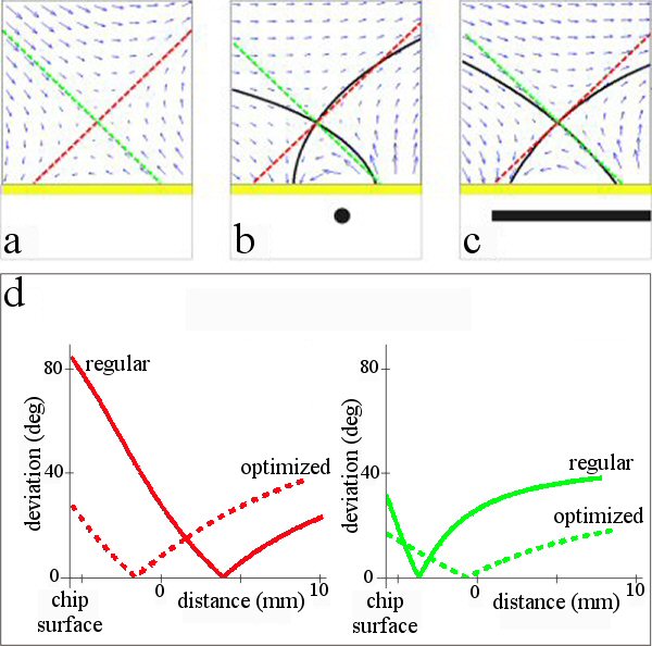 Top: Vector plots of different field configurations. (a) ideal quadrupole field, (b) thin U-wire with horizontal bias field, (c) optimized U-wire with tilted bias field. The red and green lines indicate the axes of the ideal quadrupole field, while the black lines show the approximated field axes of the U-wire configuration. The cross-section of the U-wires is drawn to scale under (b) and (c). Bottom: Angular deviation from the ideal quadrupole axes as a function of distance from the chip surface along the directions of the two 45° beams (green and red lines in (a)-(c)). The parameters for these plots are I = 55A, Bk = 14.5G (12.8G) in the plane parallel to the wire and B = 0G (3.0G) perpendicular to the wire for the regular (optimized) U.
 Because the helicity of the two 45° beams must be opposite in this configuration,the orientation of the magnetic quadrupole field must be oriented such that the field axis coincidences with one of the 45° beams. When external coils are used to provide the field this means that these usually bulky coils have to be placed at an 45° angle outside the vacuum chamber, which greatly hinders the optical access to the experiment region. Also because of the distance to the trap center, large currents (>100A) in the coils are needed, which usually means that some way of cooling the coils is necessary. Instead of such quadrupole coils we use the U-shaped copper-structure underneath the chip to create a magnetic field that in combination with a horizontal homogeneous field approximates a quadrupole field. The agreement with an ideal quadrupole field can be further improved by two changes to the U-trap. Broadening of the central bar of the U-structure and adding a component perpendicular to the chip surface to the bias field both enlarge the area where the resulting field well approximates the ideal quadrupole field.